Lab Verification of an SPI bus
One of the issues facing FPGA Design is a cost-effective way to verify the functionality of a Block design or a HDL design. A problem arises that if the engineer wishes to target Xilinx FPGAs with VHDL-2008 sources, there are limited options for creation of a robust and comprehensive test-bench when the project or hobby budget does not include a full HDL simulator. The WebPACK version of Xilinx Vivado does not include simulation support for some of the basic VHDL-2008 constructs, such as VHDL 2008 to_string() function and VHDL 2008 Sequential Conditional Signal Assignment. This prevents the usage of OSVVM or other open libraries that would accelerate and enhance the design of a robust test-bench for any size project.
Complete VHDL-2008 support simulation requires a standalone simulator such as Riviera-PRO, or ModelSim. These simulators are prohibitive in cost for an individual, though they are a decent cost for an engineering group.
One shortcut that can help with debugging of peripheral buses, with or without a test-bench, is the use of a Digital Logic Analyzer configured to probe the SPI bus signals with the peripheral attached. Digilent Inc. offers hardware for just this purpose. As my development boards are manufactured by Digilent Inc., the Arty A7 and the Zybo Z7, I chose to make use of the Digilent Inc. Analog Discovery 2, a multi-function device that includes PC-hosted Digital Logic Analyzer functionality.
To validate the QSPI bus in Extended SPI mode, I chose to monitor signals SCK, CS, COPI, CIPO with the logic analyzer. To accomplish this, the PmodTPH2 was connected between Jack JC and the extension cable that connects the PmodACL2.
Image of the assembled Analog Discovery 2 to monitor the PmodACL2 SPI
communication on Arty A7 Pmod Jack JC:
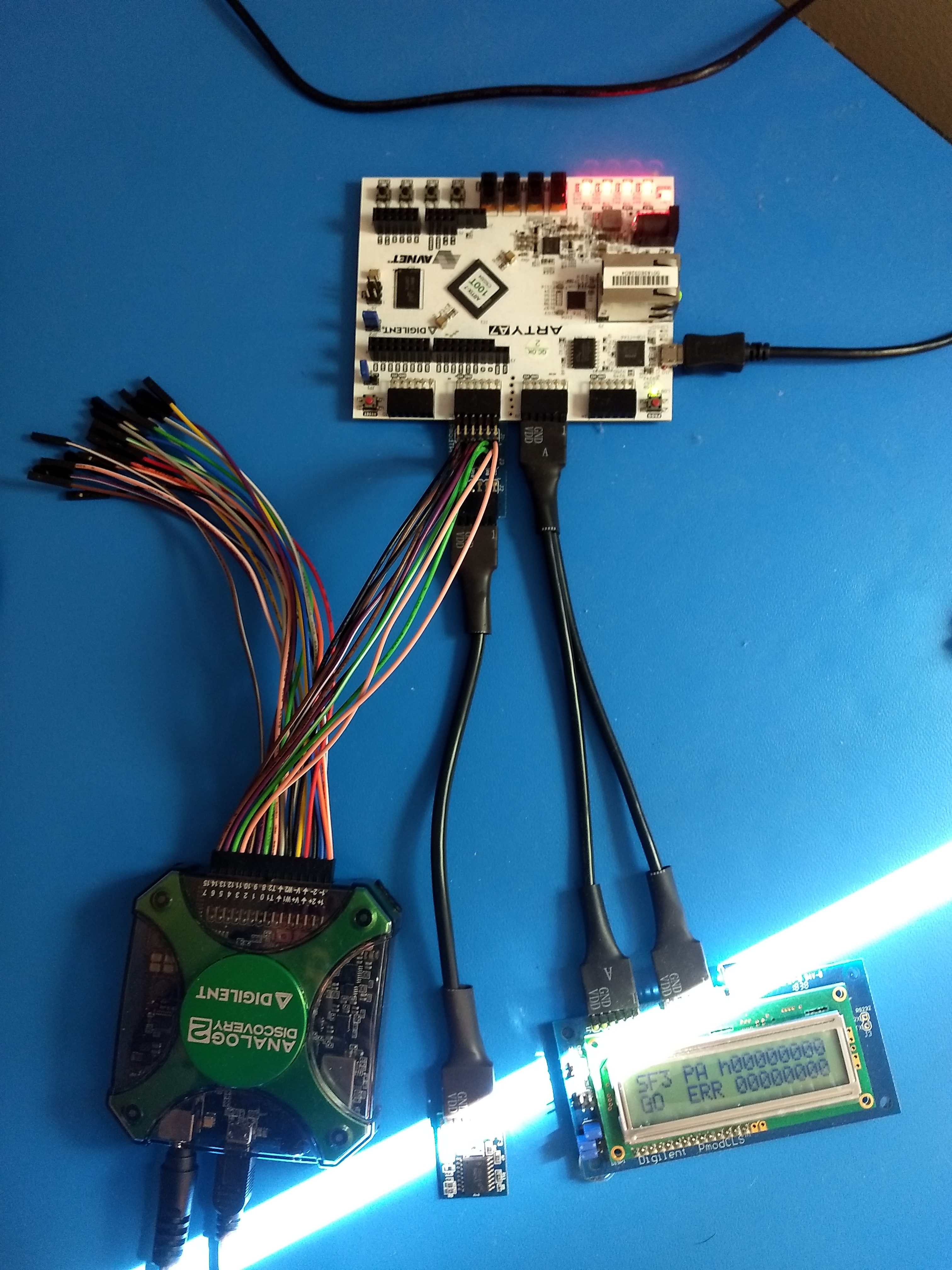
In the VHDL design of project fpga-serial-mem-tester-1 , I updated the VHDL constant c_sf3_tester_ce_div_ratio to configure the PmodACL2 SPI bus and state machines to operate at 50 KHz instead of 5 MHz. This allows the Analog Discovery to capture all operations instead of dropping probe samples on a periodic basis. With the synthesized result ready for execution and the probes connected, I executed the Digilent Inc. Waveforms application, selected protocol and SPI Spy, and specified which probe numbers correspond to a SPI bus. The Waveforms program generated a text buffer within a program window; and after the capture of execution for a period of time, the text contents were copied to a text file. I authored a Python program to parse the SPI Spy text file contents and provide a human-readable assessment of the SPI functionality.
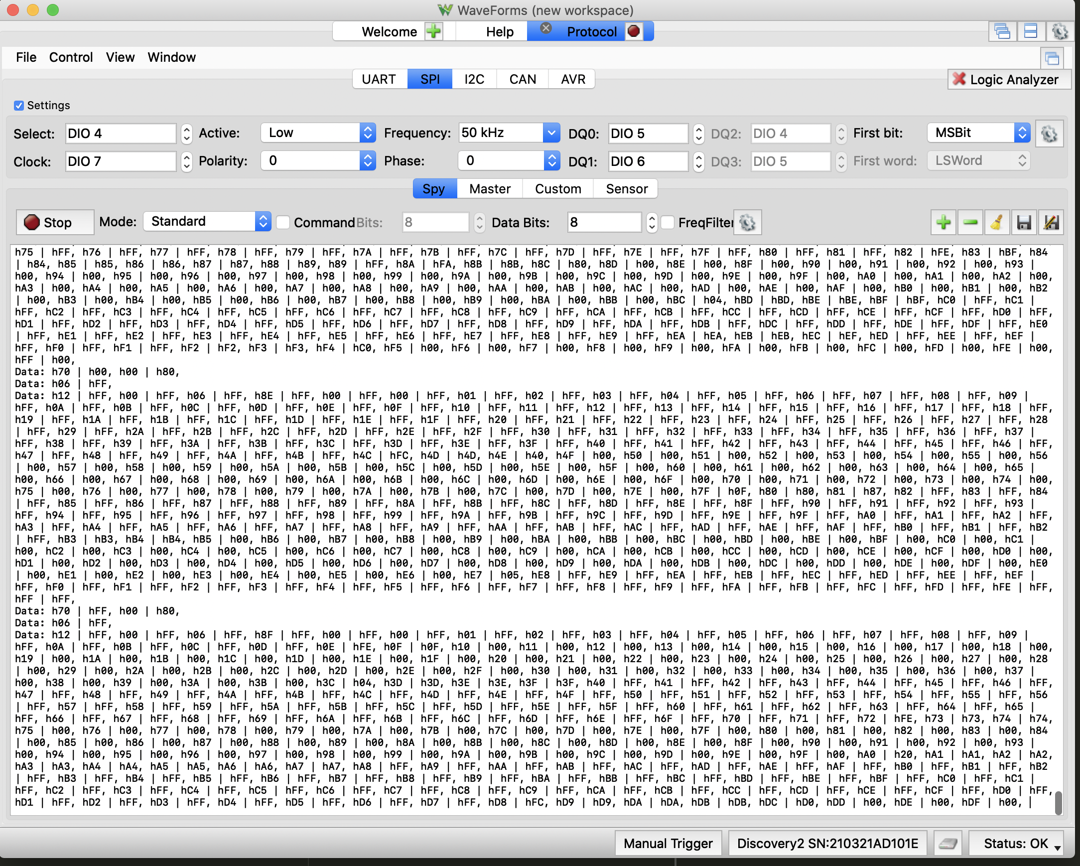
The python program can be found at: Python lab verification script
An example of checking the PmodSF3 SPI bus for correct operation of the PmodSF3 can be found at: Check of SPI Spy capture of N25Q flash programming
This procedure was then repeated to assess correct behavior of the PmodCLS. An example of checking the PmodCLS SPI bus and parsing the ASCII escape sequences and text can be found at: Check of SPI Spy capture of PmodCLS flash programming
Git Clone the fpga-serial-mem-tester-1 project and examine the Lab-Verication folder for more examples.